DC Power
GSIT 3837 Ground Fault Locator
GSIT 3837 is the updated version of GSIT 3830 ground fault locator. This patent-protected product is built based on years of field experience in different DC systems. It specially deals with current leakage DC system of high resistance below 1MΩ. It pinpoints faulty grounding where electrical lines have breakage and current lost to the ground.
GSIT 3837 Unique Advantage
· Fast location for ground fault in different DC systems
· Strong anti-interference when system is working online
· Innovative dual-range current detector with direction sensitivity
· Multi-way for location: Current direction, signal strength & phase angle
Why GSIT 3837?
Cost can be tremendous upon bad insulation or grounding in the power system. It may even cause power break-off which is costly to repair. Fast localization and elimination of grounding faults will be significant for electricians and technicians. It is also required by DIN VDE 0100-410 (VDE 0100-410): 2007-06 chapter 411.6.3.1 and IEC 60364-4-41 chapter 413.1.5.4. GSIT 3837 is developed to fast detect, track and locate virtual grounding faults on DC systems. This spares you from hours of unnecessary troubleshooting and helps to increase the reliability of your electrical equipment. It is widely used in locomotive, telecom, power utilities, etc
Composition of Signal Receiver
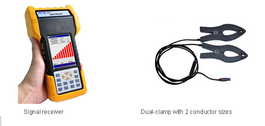
Feature · Patented technology, pinpoint current leakage fault with grounding resistance lower than 1MΩ · Innovative dual-clamp for signal receiver, each clamp has two sizes of opening jaw for different conductors · One pare of clamp working together, effective cancel capacitive interference when system is online · Precise current direction (positive or reversed) indicating for leaking currrent help fast locate the faulty grounding · Adjustable output frequency on signal receiver effectively avoids interference from DC system itself · Signal receiver can set reference in different points for signal comparision, very fast for fault orientation · Digital signal processing technoligy for detecting grounding resistance and capactitive resistance · With built-in band pass filter to bypass different interference signals in the ambient environment · No disconnection of the electrical installation, ground fault location is carried out during operation · Frequency spectrum analysis can test ambient frequencies, helps select the right frequency for the right DC system · Signal-generator with adjustable output voltage (24V~1000V) and output frequency (1~325Hz) for different DC systems · Multi-ways to indicate ground fault: sensitive current direction, phase angle, comparison of signal strength.
Frequency analysis to filter the environment frequency that might affect the testing result Oscilloscope to compare waveform before and after filtering of affected waveform Selective frequency and judgment for current direction for easier and more accurate location of faulty grounding Typical application · Railway: signal, communication and locomotive electronic equipments in railway · Communication: electronic equipments of different voltage range with faulty grounding · Power utility: DC system with faulty grounding, e.g. switchgear in substation · Others: DC system in aviation, metallurgy, auto works, household appliances and so on
Ground fault location Output voltage: 24V, 48V, 110V, 220V, 500V and 1000V Power supply Signal generator: Power consumption ≥4 hours Display Signal generator: 128×64bit LCD Signal receiver: 240×320 pixel 3.5″ TFT touch screen Memory 128M Working temperature -10℃~55 ℃ Dimension L425*W340*H130mm Weight 7.0 kg
Functional Display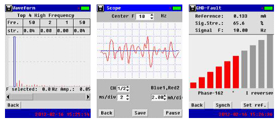
Technical specification
Output frequency: 10Hz(1Hz, 50Hz, 60Hz & 325Hz as option)
Fault location sensitivity: ≤ 1MΩ
Current detect sensitivity of AC/DC circuit: ≥ 0.5mA
Current detector:8mm(diameter) & 20mm(jaw opening), one clamp, dual-range
4200mAh/16.8V chargeable Li-ion battery
Input: AC220V/110V, output: DC16.8V/2A
Signal receiver:
2400mAh/8.4V rechargeable Li-ion battery
Charger input AC220V/110V, output:DC8.4V300mA
How does it work?
GSIT 3837 uses comprehensive ways to pinpoint the faults with the following working rules:
· Signal generator has two testing leads connected with DC system. And it injects a low-frequency current signal with direction to the DC system. This signal will flow from red testing lead, outflow from the faulty grounding point and finally flow back to black testing lead. This makes a return circuit that will be useful for signal tracing in the next step.
· Signal receiver will trace this current signal with the help of current direction judgment. Direction of current signal always goes to the faulty point. With one clamp on two busbars or two clamps respectively on two busbars, it could work effectively with strong anti-interference when system is online.
· Strength and phase angle of current signal will have big changes before and after the grounding fault. They also help pinpoint the fault.